# Building Paths
As we saw in the last section, shapes are built from paths, which are built from path elements. The most common way to build a path is to close it, i.e. to ensure that it starts and ends in the same point. However, it is possible to create open paths, e.g. only for stroking. When filling an open path, the path is closed by a straight line, basically adding a PathLine that is used when filling the path, but not when stroking it.
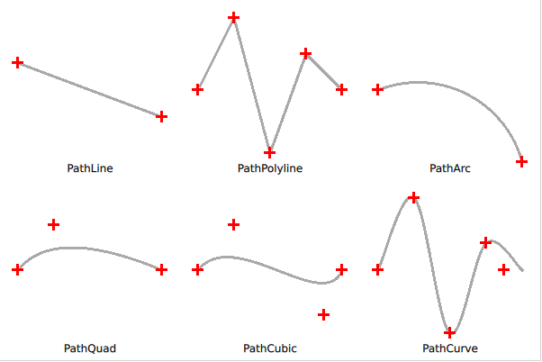
As shown in the screenshot below, there are a few basic shapes that can be used to build your path. These are: lines, arcs, and various curves. It is also possible to move without drawing using a PathMove element. In addition to these elements, the ShapePath element also lets you specify a starting point using the startX and startY properties.

Lines are drawn using the PathLine element, as shown below. For creating multiple independent lines, the PathMultiline can be used.
Shape {
    ShapePath {
        strokeWidth: 3
        strokeColor: "darkgray"

        startX: 20; startY: 70

        PathLine {
            x: 180
            y: 130
        }
    }
}
When creating a polyline, i.e. a line consisting of several line segments, the PathPolyline element can be used. This saves some typing, as the end point of the last line is assumed to be the starting point of the next line.
Shape {
    ShapePath {
        strokeWidth: 3
        strokeColor: "darkgray"

        PathPolyline {
            path: [
                Qt.point(220, 100),
                Qt.point(260, 20),
                Qt.point(300, 170),
                Qt.point(340, 60),
                Qt.point(380, 100)
            ]
        }
    }
}
For creating arcs, i.e. segments of circles or ellipses, the PathArc and PathAngleArc elements are used. They provide you with the tools to create arcs, where the PathArc is used when you know the coordinates of the starting and ending points, while the PathAngleArc is useful when you want to control how many degrees the arc sweeps. Both elements produce the same output, so which one you use comes down to what aspects of the arc are the most important in your application.
Shape {
    ShapePath {
        strokeWidth: 3
        strokeColor: "darkgray"

        startX: 420; startY: 100

        PathArc {
            x: 580; y: 180
            radiusX: 120; radiusY: 120
        }
    }
}
After the lines and arcs follows the various curves. Here, Qt Quick Shapes provides three flavours. First, we have a look a the PathQuad which let's you create a quadratic Bezier curve based on the starting and end points (the starting point is implicit) and a single control point.
Shape {
    ShapePath {
        strokeWidth: 3
        strokeColor: "darkgray"

        startX: 20; startY: 300

        PathQuad {
            x: 180; y: 300
            controlX: 60; controlY: 250
        }
    }
}
The PathCubic element creates a cubic Bezier curve from the starting and end points (the starting point is implicit) and two control points.
Shape {
    ShapePath {
        strokeWidth: 3
        strokeColor: "darkgray"

        startX: 220; startY: 300

        PathCubic {
            x: 380; y: 300
            control1X: 260; control1Y: 250
            control2X: 360; control2Y: 350
        }
    }
}
Finally, the PathCurve creates a curve passing through a list of provided control points. The curve is created by providing multiple PathCurve elements which each contain one control point. The Catmull-Rom spline is used to create a curve passing through the control points.
Shape {
    ShapePath {
        strokeWidth: 3
        strokeColor: "darkgray"

        startX: 420; startY: 300

        PathCurve { x: 460; y: 220 }
        PathCurve { x: 500; y: 370 }
        PathCurve { x: 540; y: 270 }
        PathCurve { x: 580; y: 300 }
    }
}
There is one more useful path element, the PathSvg. This element lets you stroke and fill an SVG path.
TIP
The PathSvg element cannot always be combined with other path elements. This depends on the painting backend used, so make sure to use the PathSvg element or the other elements for a single path. If you mix PathSvg with other path elements, your mileage will vary.