# Shader Elements
For programming shaders, Qt Quick provides two elements. The ShaderEffectSource and the ShaderEffect. The shader effect applies custom shaders and the shader effect source renders a QML item into a texture and renders it. As shader effect can apply custom shaders to its rectangular shape and can use sources for the shader operation. A source can be an image, which is used as a texture or a shader effect source.
The default shader uses the source and renders it unmodified. Below, we first see the QML file with two ShaderEffect elements. One without any shaders specified, and one explicitly specifying default vertex and fragment shaders. We will look at the shaders shortly.
import QtQuick

Rectangle {
    width: 480; height: 240
    color: '#1e1e1e'

    Row {
        anchors.centerIn: parent
        spacing: 20
        Image {
            id: sourceImage
            width: 80; height: width
            source: '../assets/tulips.jpg'
        }
        ShaderEffect {
            id: effect
            width: 80; height: width
            property variant source: sourceImage
        }
        ShaderEffect {
            id: effect2
            width: 80; height: width
            property variant source: sourceImage
            vertexShader: "default.vert.qsb"
            fragmentShader: "default.frag.qsb"
        }
    }
}
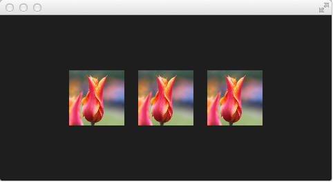
In the above example, we have a row of 3 images. The first is the real image. The second is rendered using the default shader and the third is rendered using the shader code for the fragment and vertex as shown below. Let's have a look at the shaders.
The vertex shader takes the texture coordinate, qt_MultiTexCoord0, and propagates it to the qt_TexCoord0 variable. It also takes the qt_Vertex position and multiplies it with Qt's transformation matrix, ubuf.qt_Matrix, and returns it through the gl_Position variable. This leaves the texture and vertex position on the screen unmodified.
#version 440

layout(location=0) in vec4 qt_Vertex;
layout(location=1) in vec2 qt_MultiTexCoord0;

layout(location=0) out vec2 qt_TexCoord0;

layout(std140, binding=0) uniform buf {
    mat4 qt_Matrix;
    float qt_Opacity;
} ubuf;

out gl_PerVertex {
    vec4 gl_Position;
};

void main() {
    qt_TexCoord0 = qt_MultiTexCoord0;
    gl_Position = ubuf.qt_Matrix * qt_Vertex;
}
The fragment shader takes the texture from the source 2D sampler, i.e. the texture, at the coordinate qt_TexCoord0 and multiplies it with the Qt opacity, ubuf.qt_Opacity to calculate the fragColor which is the color to be used for the pixel.
#version 440

layout(location=0) in vec2 qt_TexCoord0;

layout(location=0) out vec4 fragColor;

layout(std140, binding=0) uniform buf {
    mat4 qt_Matrix;
    float qt_Opacity;
} ubuf;

layout(binding=1) uniform sampler2D source;

void main() {
    fragColor = texture(source, qt_TexCoord0) * ubuf.qt_Opacity;
}
Notice that these two shaders can serve as the boilerplate code for your own shaders. The variables, locations and bindings, are what Qt expects. You can read more about the exact details of this on the Shader Effect Documentation (opens new window).
Before we can use the shaders, they need to be baked. If the shaders are a part of a larger Qt project and included as resources, this can be automated. However, when working with the shaders and a qml-file, we need to explicitly bake them by hand. This is done using the following two commands:
qsb --glsl 100es,120,150 --hlsl 50 --msl 12    -o default.frag.qsb default.frag
qsb --glsl 100es,120,150 --hlsl 50 --msl 12 -b -o default.vert.qsb default.vert
The qsb tool is located in the bin directory of your Qt 6 installation.
TIP
If you don’t want to see the source image and only the effected image you can set the Image to invisible (`` visible: false``). The shader effects will still use the image data just the Image element will not be rendered.
In the next examples, we will be playing around with some simple shader mechanics. First, we concentrate on the fragment shader and then we will come back to the vertex shader.